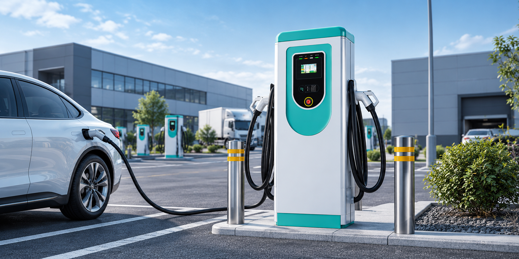
Count bays, then count failure domains. A single-connector unit serves one bay, keeps its full rating for that bay, and fails alone. A dual-connector station serves two adjacent bays from one supply and one installation — but its connectors share one power ceiling and one point of failure. Paired bays on a supply that suits a combined draw lean dual; scattered bays and per-bay independence lean single.
Key Takeaways
- Dual-connector concentrates: two bays per installation point, one shared ceiling, one failure domain.
- Single-connector distributes: a full rating per bay, independent faults, growth one bay at a time.
- The shared ceiling is arithmetic the specifier runs — 22 kW per connector, 43 kW combined on the worked example.
- The split rules under a binding ceiling are not published; close them as a written confirmation.
The Two Shapes on One Project
| Project question | Single-connector units | Dual-connector station |
|---|---|---|
| Ports per installation point | One bay per unit, one supply run and one commissioning each | Two bays from one unit, one supply connection and one installation |
| Power promise per bay | The unit’s full rating belongs to that bay alone | Each connector has its own ceiling, under one combined ceiling for the station |
| Bay pairing | Any bay, anywhere on the site, one at a time | The two bays beside the station’s position — pairing is fixed by the layout |
| Failure domain | A failed unit darkens its own bay only | One failure domain: both bays are exposed to a station-level fault |
| Growth step | One bay at a time, in any order | Two bays at a time, in pairs |
| Supply design | One circuit per unit; the design totals the units | One connection sized for the station’s combined draw |
The generic concept is set out in our guide to what a dual port EV charger is. In short: dual-connector concentrates — fewer installation points, shared ceilings, shared faults. Single-connector distributes — more installation points, independent everything.
The Shared-Ceiling Arithmetic
Run the numbers before specifying it. The EV-AC03201T carries two ceilings: 22 kW for any single connector, and up to 43 kW combined across both. One car alone can draw at most 22 kW. Two cars together ask the sum of what each accepts: an 11 kW car beside a 22 kW car asks 33 kW — under the ceiling, both served in full. Two cars that each accept 22 kW ask 44 kW against a 43 kW ceiling — the only common pairing where the ceiling binds at all.
When it binds, the station’s dynamic allocation divides the total; the listing names that capability and nothing more. Its moment-to-moment rules — whether an even split, a demand split or a first-arrival priority applies — are not published, so a specification that assumes one answer must close it as a written confirmation with the supplier. The principle — sharing divides a supply rather than creating power — is the one in our explainer on whether load balancing increases charging speed. Single-connector circuits carry their own sizing rule: charging is a continuous load under the NEC, so a 32 A unit takes a 40 A breaker (125%).
The Options in the EVDANCE Range
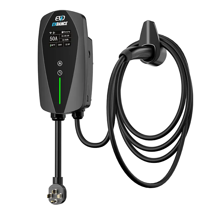
The dual-connector option is the EV-AC03201T: a floor-standing station with two Type 2 connectors, up to 43 kW shared (22 kW per connector), OCPP 1.6J, RFID and an IP54 enclosure. Its 7-inch touchscreen is the driver display — it is not a payment terminal, and no billing platform is stated for the station; driver payment is an operator arrangement confirmed separately. The single-connector options include the EV-ACT3204PE 22 kW three-phase wallbox (tethered Type 2 cable, RFID and app) and the EV-ACT5006T NACS wall charger at up to 48 A with a 25 ft cable. Projects can mix both shapes — duals on paired bays, singles on scattered ones — and work through a layout via our commercial EV charging page or contact us.
Frequently Asked Questions
Does a dual-connector station halve each car’s charging speed?
No. Each connector’s ceiling is 22 kW, and the combined 43 kW ceiling only binds when both cars together ask for more than it — in practice, two high-acceptance cars at once. Most pairings are limited by the cars themselves, not by the sharing.
What happens if one connector of a dual station fails?
Connector-level fault behaviour is not stated in the listing, so do not specify around an assumption. Plan the station as one failure domain — both bays exposed — and confirm in writing what one connector’s fault does to the other before the layout relies on it.
Can one project mix single-connector and dual-connector units?
Yes, and many layouts should: dual stations where bays come in pairs, single units where bays are scattered or added one at a time. The electrical design totals both shapes; the specification must say which bays get which.
Related Reading
- What Is a Dual Port EV Charger? How It Works and How to Choose
- Does Load Balancing Increase EV Charging Speed?
- What Is the Best Commercial EV Charging Station? How to Choose